Selecting Louvers and Dampers
Many of us have been selecting Louvers and Dampers out of habit without remembering the basics and this little piece is a refresher.
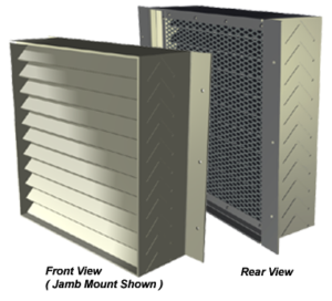
The purpose of the Louver is to have an aesthetically pleasing interface to allow air into (or out of) the building while keeping “non-air out” (ie, birds, bugs, people), as opposed to a large opening on the side of the building. The biggest challenge of the “non-air” is water for inlet applications when it is raining.
Fact 1: Free area. Free area is the open space that allows air in which is net from the blades of the louver. In other words, if you have a 12” x 12” opening and there are a handful of blades inside, your opening is 1 square foot, but your free area is somewhat less. Free Area Velocity is calculated simply by Dividing CFM/Free Area Velocity
Free area is important, and along with cfm, will determine the free area velocity of the air through the louver. As you size the louver smaller, the free area velocitywill increase which will increase the pressure drop. Water infiltration is directly related to a louver specific free area velocity.
Louvers can be Fixed or Adjustable; If fixed, a matching damper is recommended which can be downstream or combination (ie, the louver won’t move, only the damper behind will; 1 installation, not separate for the louver and damper)
Louvers come in “drainable”or non-drainable.Drainable units have gutters in each blade to allow excess water to collect, that water then flows into jamb downspouts and out the front of the louver to allow a higher free area velocity before water infiltration.
Fundamentally there are 4 blade sizes: 2” deep, 4” deep, 5” deep and 6” deep.
The most common blade types are as follows:, Non-Drainable, Drainable, or Sightproof (which include Wind Driven Rain typically).
See the chart below, courtesy of United Enertech data. Their 4” drainable gives the best value and performance.
BASED ON A 48″ X 48″ Louver, using 6416 cfm,
| FLD-2 | FLD-4 | FLD 6.1 | D-HFA-6 | EL-2 | EL-4 | EL-6 | |
| 2″ drainable | 4″ drainable | 6″ drainable | high free area | 2″ non-drain | 4″-non drain | 6″ non-drain | |
| Free Area (sqft) | 8.66 | 8.02 | 8.71 | 9.55 | 8.82 | 8.42 | 8.26 |
| Free Area Velocity (fpm) | 740.8 | 800.0 | 736.6 | 671.8 | 727.4 | 762.0 | 776.8 |
| Static Pressure Drop (in H20) | <.1 | <.1 | <.1 | <.1 | <.1 | .1-.12 | .1-.12 |
| Beginning Point of Water Penetration (fpm) | 805 | 1250 | 1250 | 915 | 524 | 995 | 834 |
- As you can see from the above chart, at 6416cfm both the 4″ and 6″ drainable louvers produce free area velocities well below the beginning point of water penetration (1250fpm) while maintaining a pressure drop less than 0.1″wg. This would indicate that these two louvers have a superior ability to prevent water infiltration compared to the other models.
- The D-HFA-6 allows more air for the same nominal Legnth and Width so if space is a premium, you can consider make the wall opening smaller for a similiar performance
- The EL-2 will have Water Penetration Potential as selected. While lowest first cost, not a good choice. (The EL is more designed for Natural Ventilation)
OPTIONS AND ADDITIONAL NOTABLES
- Driving Wind/Rain Construction. Designed to be superior in water penetration protection and AMCA rated by the amount of water that passes through them in a wind driven rain test. Note that AMCA always recommends taking possible water infiltration into account and to design your system accordingly
- Mullion For Mating Extra-Large Louvers
- Filter Rack
- Higher Gauge Blade= .125g Vs .081
- Extended Sill- Option To Prevent Water Run-Off From Streaming Along The Exterior Wall
- Split Deflection- Allow Air In 1 Louver To Handle 2 Angles For Inlet/Out Applications
- Security Grille
- Blast Resistance
- Glazing Adapter
- Panel Wall Adapter
- Paint option: Baked Polyester- Doesn’t Chip Vs Kynar- Better UV Light Protection
Dampers
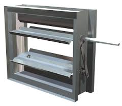
Dampers are the controlling means of air flow.
The damper can be opened/closed in the following way:
- Manual: a crank to adjust the blades; typical for balancing- set and forget
- Gravity or spring loaded: the air flow will push the damper open and the damper will close upon no flow
- Motor activated: An actuator motor and arm which will drive the damper open and closed (and in between) based on an electrical control signal. Actuators can be pneumatic, line voltage or run off of control voltage
Damper construction can be Crimped (cheapest) or Air Foil type for more robust applications.
In some applications, the damper can be arranged in an opposed orientation (so the dampers are shaped in a v and closes together to keep air flow uniform) Or Parallel (the blades are parallel to each other)
Things to consider for dampers:
Leakage- do you need Jamb and Blade seals? If you don’t have them, the air will leak past despite the damper being closed
Did you consider the blade passing the sleeve when open? There are options for shorter blades that don’t protrude (ie, UE Thinline Damper)
Please call or email us for additional info regarding
Fire and Smoke Dampers & Combination Fire/Smoke dampers


